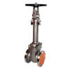
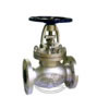
Description:
The valve is designed for using under high pressure and high temperature condition. The nominal pressure of this product should be Class 150LB- 1500LB. The bellows of this valve has long cycle life. It has two secondary stem seals. And the backseat of forged steel bellows sealed valve is in open position with superior seating faces. Bellows monitoring port is optional. In addition, the body trims and bellows material is available on your request. We adopt graphite packing for this product.
Technical Data of Forged Steel Bellows Sealed Valve:
a. Basic design: API 602 & MSS SP-117
b. Socket weld end: ASME B16.11
c. Threaded end: ASME B1.20.1
d. Flange end: ASME B16.5
e. Face-to-face dimension: ASME B16.10
f. End-to-end dimension: MFR.STD
g. Inspection and test: API 598
Part Materials of Forged Steel Bellows Sealed Valve:
| NO. | Part | Materials |
| 1 | Body | ASTM A105 |
| 2 | Seat ring | Type 410 SS |
| 3 | Wedge | Type 420 SS |
| 4 | Stem | ASTM A182 F6a |
| 5 | Bonnet | ASTM A105 |
| 6 | Split pin | Carbon steel |
| 7 | Gland bolt | Type 410 SS |
| 8 | Gland flange | Carbon steel |
| 9 | Thrust collar | Type 410 SS |
| 10 | Handwheel | Malleable iron |
| 11 | Handle nut | Carbon steel |
| 12 | Nameplate | Aluminum |
| 13 | Stem nut | Aluminum bronze |
| 14 | Grease fitting | Copper alloy |
| 15 | Nut | Carbon steel |
| 16 | Gland bushing | Type 410 SS |
| 17 | Pin | Type 410 SS |
| 18 | Packing | Graphile |
| 19 | Bellows assy.(1) | Type 321 S.S. |
| 20 | Extension | ASTM A105 |
Socket Weld/Threaded Gate Valves:
| Size | d | A | d1 | h | L1 | H(OP) | D | |||
| In. | 150lb-800lb | 1500lb | 150lb-800lb | 1500lb | 150lb-800lb | 1500lb | ||||
| 1/2″ | 10 | 34 | 21.7 | 10 | 82 | 89 | 183 | 330 | 100 | 100 |
| 3/4″ | 13 | 40 | 27 | 13 | 90 | 96 | 286 | 343 | 100 | 100 |
| 1″ | 18 | 49 | 33.8 | 13 | 92 | 130 | 319 | 431 | 125 | 125 |
| 1 1/2″ | 32 | 65 | 48.6 | 13 | 130 | 138 | 393 | 575 | 160 | 200 |
| 2″ | 38 | 78 | 61.1 | 16 | 150 | 224 | 452 | 659 | 180 | 250 |
Flange Gate Valves:
| Size | 150lb | 300lb | 600lb | 1500lb | ||||||||||||||||||||
| In. | d | L2 | C | D | H | WT | d | L2 | C | D | H | WT | d | L2 | C | D | H | WT | d | L2 | C | D | H | WT |
| (kg) | (kg) | (kg) | (kg) | |||||||||||||||||||||
| 1/2″ | 10 | 108 | 89 | 100 | 183 | 4.1 | 10 | 140 | 95 | 100 | 183 | 5.2 | 10 | 165 | 95 | 100 | 183 | 5.5 | 10 | 216 | 121 | 125 | 343 | 8.9 |
| 3/4″ | 13 | 117 | 98 | 125 | 286 | 5 | 13 | 152 | 117 | 125 | 286 | 6.9 | 13 | 190 | 117 | 125 | 286 | 7.6 | 13 | 229 | 130 | 125 | 343 | 11.2 |
| 1″ | 18 | 127 | 108 | 165 | 319 | 6.9 | 18 | 165 | 124 | 165 | 319 | 8.7 | 18 | 216 | 124 | 165 | 319 | 9.7 | 18 | 254 | 149 | 160 | 343 | 14.1 |
| 1 1/2″ | 32 | 165 | 127 | 180 | 393 | 12.1 | 32 | 170 | 155 | 180 | 393 | 15.5 | 32 | 241 | 155 | 180 | 393 | 16.3 | 32 | 305 | 178 | 180 | 575 | 22.1 |
| 2″ | 38 | 178 | 152 | 200 | 452 | 18.5 | 38 | 216 | 165 | 200 | 452 | 22.1 | 38 | 292 | 165 | 200 | 452 | 23.6 | 38 | 368 | 216 | 200 | 659 | 33.6 |
Statement: this information is just for reference, for detailed information, please contact us.

